 Below is a render of what the model looks like at the moment.
 I also attempted to model a hand for my animation. I used reference images and extruded a cylinder to create the hand.
  This is what the hand looks like at the moment.
 Below is a render of what the model looks like at the moment.I also attempted to model a hand for my animation. I used reference images and extruded a cylinder to create the hand. This is what the hand looks like at the moment.
 Here is the finished Jet fuel truck this is my third model for my trailer. I finished modelling the front of the truck including the headlights. I didn't spend too much time on the headlights as they will not be viewed close up.
 Front view of the truck
 Rear view of the truck
 Above is a render of the truck as it looks at the moment. With the rear tank part of the truck finished I started to add the materials to the truck. As I needed to put the logo onto the side of the truck I used an UV unwrap modifier and selecting the polygons of different sections of the model I unwrapped each section and arranged the separate map sections in the image.
 Here the polygons making up the inside of a compartment on the back of the truck is selected on the left you can see a window the with sections of the truck that have already been unwrapped and the polygons that make up the selection highlighted in red in a bunch on the left.
 Choosing the option of unwrap mapping 3ds max unwraps the selected polygons to create a net that when folded back up creates the shape. The image above shows in red the unwrapped map selected. This can then be scaled and placed in the image area to be rendered as a guide image.
 After unwrapping all of the sections I arranged them so that they fitted in the image area and rendered the UV guide as a PNG so that it would have a transparent background. I opened this in Photoshop, here I added the logo and detailing to an image using the guide image to know where to place them. Saving the created image without the guide and using it as a material for the object in 3ds max the separate sections will display on different parts of the model.
 I had some problems with UV unwrapping where parts of the mesh were joined in the wrong way and where I had used the wrong mapping type so was unable to add the textures I had wanted to that edge. Also the guide image was too small so that when I applied the material to the object the textured looked blurry. To fix this I had to increase the size and try again.
 This is a render of the truck showing how far I have got with the modelling. The front of the truck still needs to be finished and the headlights created and the door finished off. As well as this I still need to add the final materials add more detail.
 I added smoothing to the front of the truck and adjusted the creasing of some of the edges to decrease the smoothing applied to these sections.
 I decided to remove the door from the truck cab mesh so that it was a separate object. this would make it easier to model the truck and would allow me to animate the door opening if necessary.
 I didn't post any screenshots of how I created the truck wheel model at the time so I am posting them here. Above is the section of rim that I created for the wheel.
 I used the rotate tool to rotate the section around so that the it was next to the original section while holding the shift key.
 This brought up the clone object panel and I inscreased the amount of copies to 9 to create the full circle.
 This is the final object after I had used target weld to join the vertices at the edges of the sections together.
 Above is a render of the rim for the wheel. It has some slight bumps around the edge, as I think that the orginal cylinder that I used didn't have enough sides, but this are less noticable with the tyre in place.
 Here is a screenshot of the tyre mesh this was created using a tube primitive.
 Above is a render of the tyre with out the rim in place. Below is a screenshot of the final tyre model.
 For my third model for the assignment I am creating a Jet fuel truck. I set up reference planes with some images that I found. These images weren't very good as they are not exactly straight and I could only find images of the side and back of the truck so I had to use them as best I could.
 In object properties I set the objects to transparent so that I could see the reference planes through the model.
 I added a mesh smooth modifier to the rear of the truck but this smoothed all of the mesh. I selected edges that I wanted to keep from being smoothed and adjusted the crease setting to 1.
 To model the cab I started with a box and by extruding and adding loops I created the shape of the cab.
 The front of the truck is proving difficult as I am having to model from reference images that I have found rather than using the reference planes that I had set up.
 This is the truck so far, I have put the wheels that I modelled earlier in place so I could see how the mesh needed to be modelled around them.
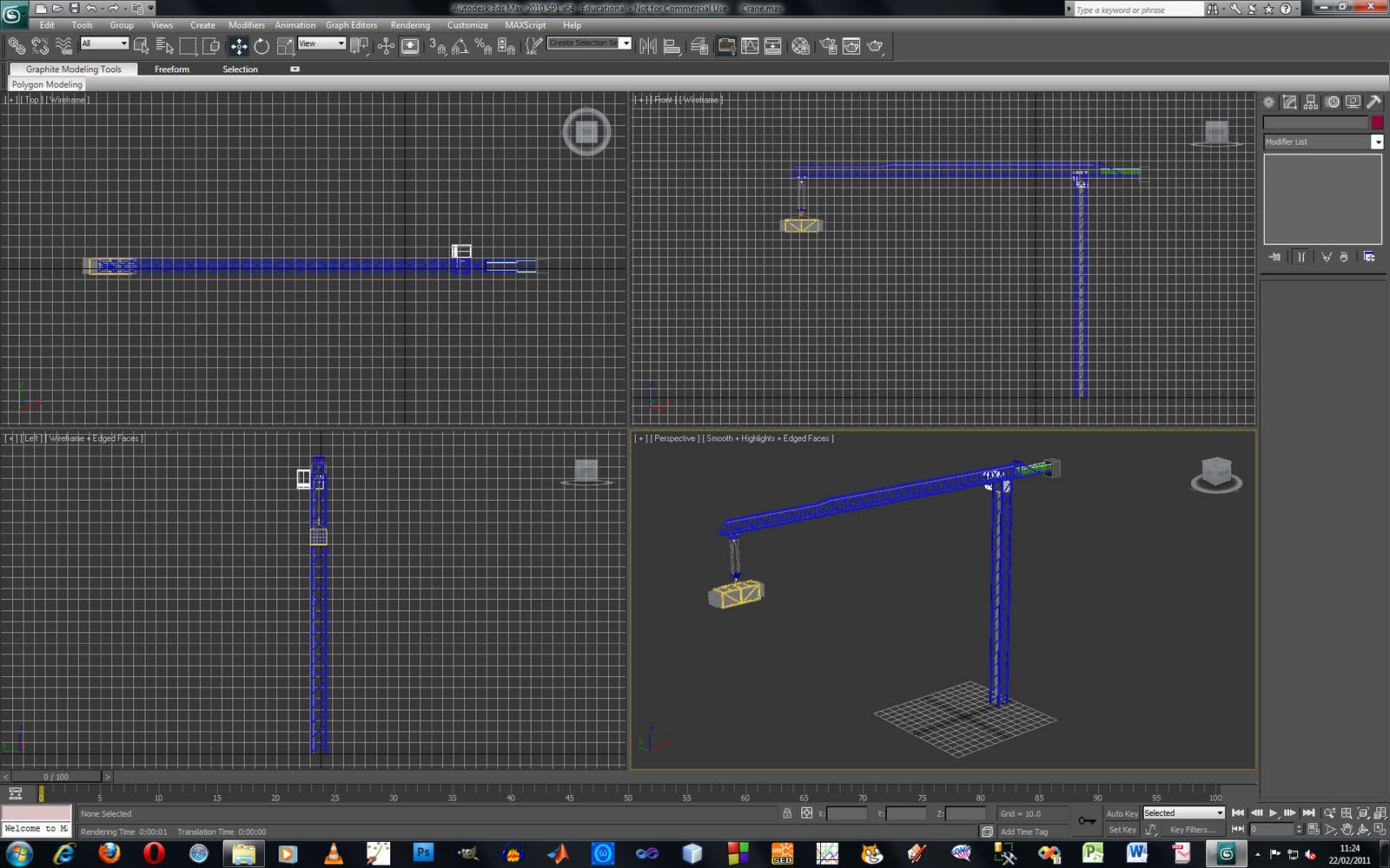
 Here is my finished crane model, this is my second model for my trailer. I took the parts that I had modelled earlier and when they were in place I grouped them together.
 I created a ground plane so that the crane had something to stand on and so that there was something to receive the shadows. I used soft selection to model some bumps into the plane and added a noise map into the bump map to make a sand/dirt type of material.
 I added materials to the crane. I used texture maps for the pipes and the crane and used architectural materials for the glass on the cab and the concrete on the counterweight. I am quite happy with the materials that I have created as when looking at the crane from a distance they look ok but if I have enough time I may change them later as the crane I will need a close up in my animation.
 I set up a daylight system to create a sky and quickly add light to the scene. Below is a render of the crane at a different time setting. Setting up the lights in the scene improved the look of materials and made the model look more realistic.
 I added temporary materials so that I could easily change them later without having to assign the materials to all of the sections later when there would be lots of different objects in the way. I deleted the end polygons so that I would be able to weld the section together.I used clone to copy the section that I had created for the amount of times that wanted and attached the sections into one object. I then used the target weld to join the vertices of the separate sections together.
 Here is a hook for the crane. I drew out the hook in illustrator and then imported it into 3ds max and used an extrude modifier to create the shape. I adjusted the shape of the hook so that the edges were curved instead of being flat.
 For the hook section I used two symmetry modifiers to mirror the mesh in two planes so that I only had to model a quarter section. I started with a box and modelled from there.
 I modelled the pulleys by starting with a cylinder and using the extrude and inset tool. I created the hole in the middle by extruding both sides inwards and joining the vertices in the middle. I used a symmetry modifier so that both sides would be exactly the same.
  I had trouble making the cage to carry the pipes. I used a cube and used the inset and extrude tool to extrude the middle section inwards. I then had to adjust individual vertices, add extra loops and weld vertices to create the correct shape. I used symmetry to mirror the other half so I only had to model one side.
 I used tubes for the pipes and added an image as a material. I cloned the object to create the group of pipes.
 To model the rim of the wheel I started with a cylinder and deleted part of the mesh so that I was left with 1/10th of the circle. I modelled the bolt and holes in this small section, leaving the pivot point at the center. When I had finished modelling this section I used the rotate tool to clone the section around in a circle to create the whole wheel. I rotated the cloned section so that it was next to the original part that I had made and by increasing the amount of copies to be cloned I created the rest of the wheel. This required a bit of trial and error to get the wheel to join. To create the full circle the mesh had to overlap a bit, I fixed this by joining up the vertices where the sections of wheel met.
 Adding materials to the rim caused some problems as it was difficult to select the middle section of the wheel. The rim of the wheel is quite high poly so I will use this wheel for closeups and may have to model another wheel using a simple cylinder with an image texture for the long shots.
 Here is a card table that is one of the models for the assignment that I have modelled, this will go with the playing cards and poker chips chips that I have already modelled.
 I found modelling the card table quite easy, I used illustrator to draw out a path for the shape of the table and used the loft tool to create the edge around the table. I extruded the same path to create the center of the table. The legs of the table were created using by extruding a cylinder into the shape that I wanted to create.


