Showing posts with label tutorial. Show all posts

Tuesday, 29 March 2011

Bowling

Here the reactor was used to create a bowling animation. The pins, ball and alley were added to the the rigid body collection and the mass were adjusted for the separate items. Autokey was used to move the bowling ball forward so that it had some forward force and spin was added to the ball.
Then when the reactor was previewed the ball fell onto the alley and rolled into the pins knocking them down. Adjusting the collision tolerance stopped the pins from falling partly into the floor.

Below is the animation from two different angle, some basic materials were added the scene so that it wasn't just plain grey.


Reactor

This is my first attempt at using the reactor. Two boxes were created one for the ground and the other for a falling box. A rigid body collection was added and the two box objects added to it.

In the utilities tab I set up the reactor here I adjusted the mass, friction and elasticity for the box and the ground. keeping the mass of the ground at 0 and making the box more then zero meant that the ground would not fall.

Clicking on 'preview in window' button displayed a window that displays the simulation, pressing p plays the simulation. When this is correct the create 'animation button' can be pressed to turn the simulation into keyframes. Then this can be rendered, here is a render of of the box falling.


Tuesday, 22 March 2011

Yawn

Using the morpher expressions that I created for the head model I have tried to animate the character yawning.

Morpher

I imported the head model and converted it to a editable poly. I cloned the head 7 times and kept one of the heads as the main head, the other ones will be used to create the different expressions. I modified the polygon of the heads to create mouth open, mouth closed, left eye closed, right eye closed, left eyebrow up, right eyebrow up and named the heads so I could identify them.

I added a morpher modifier to the original head and then right clicking in one of the empty boxes click pick from scene and chose one of the heads. I repeated this for the rest of the heads. Next to the boxes is a number box that can be changed between 0 and 100. At 0 the head with the modifier mesh looks normal but at one hundred the mesh has moved to the same place as the selected head. I added a turbosmooth modifier above the morpher modifier to smooth the head model.

By animating these values, using autokey, facial expressions can be created. Using the curve editor and the dope sheet helps when animating as you can exclude the separate keyframe tracks as it is hard to tell what keyframe on the time line is for what expression as they are all shown in the same colour.


Facial expressions
Default

Eyebrows up

Eyes closedMouth closed

Mouth open
Wink

Tuesday, 15 March 2011

Animating with Bones

I imported torso object and added a turbosmooth modifier to it. I added bones and positioned them in orthographic view (top, left and front) by rotating and moving them into place.

I named each of the bones so that they could be easily identified. I adjusted the front, side and back fins for each bone and then repeated the steps for the other arm.

I selected the end bone that is joined to the hand bone and selected the IK limb solver and then selected the first bone (upper arm).

Adding a skin modifier to the torso model and selecting the bones that had been created allowed the torso model to move when the arm bones were moved.

A bone was added for the body and included in the skin modifier like the other bones so that the body would not deform when moving the arms.

I edited the envelopes for each bone to define how much of the torso mesh should deform when moving the arm bones.

Red is used to show the part of the mesh that will be effect most by that bone and the blue parts will be least affected by the bone.

It was difficult to adjust these properly so that arm would move properly without the other parts deforming.

Tuesday, 8 March 2011

Animating along a path

I used a teapot object and then drew a path for the teapot to follow. With the teapot selected I went to Animation>Constraints>Path constraints and then selected the path that I had created.

In the motion panel under path parameters, I checked the follow and bank check boxes to make the teapot rotate to follow the path and make it bank into the corners.

The same method can be used with a camera to make it follow a path. With a target camera the target point can be made to follow the the path or the camera by selecting the separate part then using the path constraints.


Rendered animation of the teapot following a path

Animation basics

For my first attempt at animating in 3d studio max I used auto key to create the animation of a ball bouncing.
Using the curve editor I adjusted the shape of the curve and used the fast tangent pre-sets on the upwards bounce of the ball. Using the out of range types I set the type to cycle so that it would repeat throught out the animation. I cloned the ball two times to create 3 balls.

I changed the dope sheet to edit ranges and with the spheres selected I changed the length of the bounces for the separate balls and moved the starting positions so that they would start on different frames so that they do not look exactly the same.

I rendered the animation to an AVI this is shown below. The balls do not squash when they hit the ground. This is something that could be added later to make the ball's bounce look more realistic.

Tuesday, 22 February 2011

Cameras

The tutorial this week was to learn how to set up cameras in a scene. There are two types of camera target and free. Target cameras have a target which the camera focuses on, that can be moved around but the free camera does not. I added a camera using ctrl+c but cameras can also be added from the cameras menu.

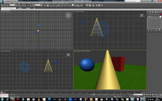
When a camera has been created, one of the viewports can be changed to the camera view. Inside this viewport there are tools that can be used to adjust the camera settings. These are dolly camera, perspective, roll camera, field of view (FOV), truck camera, orbit camera. More camera setting can be adjusted in the modify panel.

I created a basic scene using a plane, a sphere, a cone and a cube and adjusted the camera settings. I used the dolly camera and orbit camera to move the camera intp to the place that I wanted it.

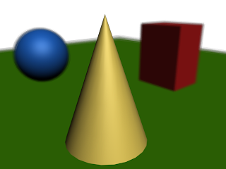
In this first image I used a 35mm lens type and adjusted the camera with the perspective tool. I enabled DOF (Depth of field) in the camera settings to blur the shapes further from the camera. I adjusted the target of the camera so that it was set inside the cone so that it would be in sharp focus.

The second image is the same camera set up as the first but the DOF has been turned off.
The third image camera set up is the same but I have used the perspective tool to change the perspective of the camera. The shapes in the background look as though they are closer to the cone in front.

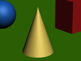
The fourth image camera set up is the same an I have again used the perspective tool to change the perspective of the camera. Now the shapes in the background look as though they are further away from the cone in front.

Wednesday, 16 February 2011

Lighting

This tutorial involved lighting a pumpkin model that was provided for the tutorial. An omni light was added inside the model to create the effect of a candle inside of the pumpkin.

I changed the intensity and colour to make it look like a candle and turned on the shadows and adjusted the density so that they were not so dark. I added another light behind the pumpkin and added an atmosphere and a volume light to make a smoke effect behind the pumpkin, this light was changed to a green colour to make it look spooky.

Here two lights were used one blue and one red, these were placed above the objects. All of the objects in the scene were changed to a white material. The cylinder was excluded from the effect of the blue light and was the only object included to be effected by the red light. The cylinder is red as it has only the red light shining on it if the cylinder wasn't excluded from the blue light it would be a purple colour. This shows how lights can be used to only effect certain objects with the scene.

This tutorial involved setting up a daylight system a sky was added to the scene and architectural materials were used on the objects. The render had to be changed from the default scanline renderer to Mental ray before this could be done. This was a quick way to light a outdoor scene produced a good result.

Friday, 11 February 2011

Materials

I followed the tutorials on Jo's blog. Here I have used material IDs and a multi/sub-object material to add different materials to a teapot object. I will need to use this method on the objects that I make for my animation especially the poker chips that will need different materials mapped to different sections of the mesh.
Below is a render of a highly reflective material that used an image as a reflection map.

Tuesday, 8 February 2011

Making Leaves Using Mapping Techniques

This leaf was created using mapping techniques. A mask was made in photoshop from the shape of the leaf image. The original leaf image was applied to the plane in 3ds max and used as a bump map and the mask was applied to make the outside of the leaf transparent.

The plane was shaped to make it more leaf shaped using an Edit poly modifier and using soft selection to select the vertices to rotate parts of the leaf.
Final rendered leaf

Friday, 4 February 2011

Boolean, loft and arrays

I have followed the tutorials on Jo's blog to learn new techniques as I am finding the modeling quite difficult.

Here a letter A was cut out of a cube object using boolean subtraction. This was also the first time that I had used the text tool.
Boolean image render


The coat hanger was created with a spline line formed into the coat hanger shape and then the loft modifier was used to add depth to the line. This loft tutorial turned out better than my previous attempt with the helix shape as the different parts of the object touched, I think that this may have been because the circle shape that I used for the lathing was too large.
Above is what the coat hanger looks like rendered

An array was used to make duplicate copies of an object. The array diaglogue box seemed quite complicated with all the boxes and setting.

Tuesday, 1 February 2011

Using Reference Planes

This is my attempt at modeling a tank using reference planes. Setting up the reference planes was quite difficult. I set up the planes with an image of a tank on that I used to help making the model.

I set the objects to transparent so that I could see the references images through the objects.

I worked in the top and left view for modelling and used the perspective view to see how the model was looking.


Above is a screenshot of the model that I have created, below is a render of the 3d model so far with default materials.

Modelling from shapes

These models were made from shapes in 3d studio max. The chess piece and the flower like shape was created from paths that were imported from illustrator files. An extrude modifier was then used to make the path into a 3d shape. The chess piece was modelled using lathe modifier and the loft modifier was used for the spiral shape.

I found the lathe, extrude and loft modifiers easy to use, although I had one problem where the chess piece came out squashed, this was because I scaled the path before adding the lathe modifier.